What is In-Circuit Testing (ICT)?
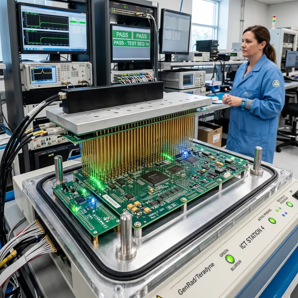
In-circuit testing (ICT) is an automated testing method used to verify the electrical integrity of populated printed circuit board assemblies. ICT uses a bed-of-nails test fixture containing spring-loaded probes that contact designated test points on the PCB, enabling rapid electrical measurements of individual components and interconnections.
ICT is considered the gold standard for manufacturing defect detection, capable of identifying problems that visual inspection and even Automated Optical Inspection (AOI) might miss — such as wrong-value components, reversed polarity, and internal solder opens.
What Does ICT Detect?
In-circuit testing identifies a comprehensive range of manufacturing defects:
- Solder shorts: Unintended solder bridges between adjacent pins or pads
- Solder opens: Missing or insufficient solder joints
- Wrong component values: Resistors, capacitors, or inductors with incorrect values
- Missing components: Parts that were not placed during SMT or THT assembly
- Reversed polarity: Diodes, electrolytic capacitors, or ICs installed backwards
- Incorrect components: Wrong part numbers loaded on the line
- Trace opens/shorts: PCB fabrication defects
- Connector integrity: Proper pin-to-pin continuity in connectors
How ICT Works
The Test Fixture
A custom test fixture is built for each PCB design. The fixture contains spring-loaded probes (pogo pins) positioned to contact specific test points, component pads, or via holes on the board. When the board is loaded, the fixture provides electrical access to hundreds of test points simultaneously.
The Testing Process
- The assembled PCB is placed into the test fixture
- Probes make contact with designated test access points
- The ICT system applies stimulus signals and measures responses
- Component values are measured and compared against programmed limits
- Continuity and isolation tests verify all interconnections
- Results are logged and boards are sorted pass/fail in seconds
Testing Speed
A typical ICT test cycle takes 5-30 seconds per board, depending on complexity. This makes ICT highly efficient for production-volume testing, enabling 100% inspection without bottlenecking the assembly line.
ICT vs Other Testing Methods
| Method | Detects | Speed | Best For |
|---|---|---|---|
| ICT | Electrical faults, wrong values | Very fast | Manufacturing defects |
| AOI | Visual defects, placement errors | Fast | Solder quality, missing parts |
| Functional Test | Overall board function | Variable | System-level verification |
| X-Ray | Hidden solder joints | Moderate | BGA, QFN inspection |
ICT in the Manufacturing Flow
In-circuit testing is typically positioned after soldering (both reflow and wave) and AOI inspection. The recommended test flow is:
- SMT Assembly → Reflow → AOI
- THT Assembly → Wave solder → AOI
- In-Circuit Testing (ICT)
- Functional Testing
- Conformal coating (if required)
- Final inspection and packaging
ICT at TOS Lanka
TOS Lanka's test and inspection facility provides comprehensive in-circuit testing capabilities:
- YAMAHA automated optical inspection systems
- ICT systems with custom fixture design capability
- Functional testing stations with firmware upload
- 100% testing protocols for medical, automotive, and industrial electronics
Ensure zero-defect quality in your electronic manufacturing. Contact TOS Lanka to discuss testing solutions.